Products
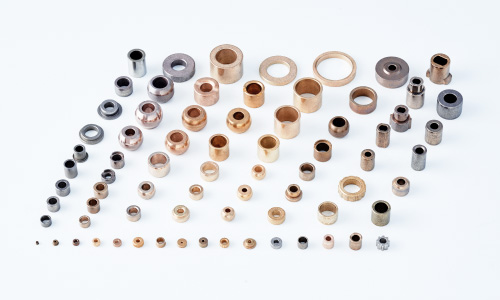
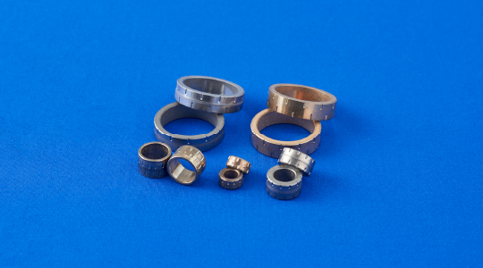
Diamet’s Oil-Impregnated Sintered Bearings / Sintered Bearings
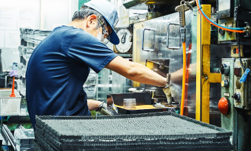
We manufacture high-precision, high-quality, and high-performance sintered bearings and oil-impregnated sintered bearings that take advantage of our unique powder metallurgy technology and self-manufactured high-precision die assemblies as the top brand in sintered bearings. We also produce oil-impregnated bearings, as well as dry bearings that can be used in a high-temperature or clean environment where oil cannot be used, in addition to high-performance sintered bearings that feature corrosion resistance. Through our unique material, manufacturing, and evaluation techniques, we offer optimum products for a variety of different conditions and environments in accordance with the intended use.
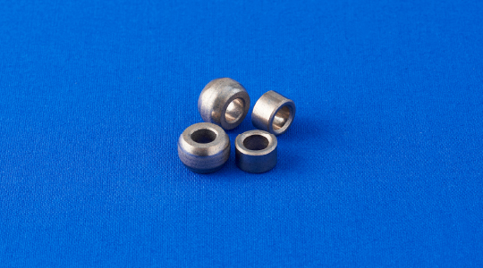
About Oil-Impregnated Sintered Bearings
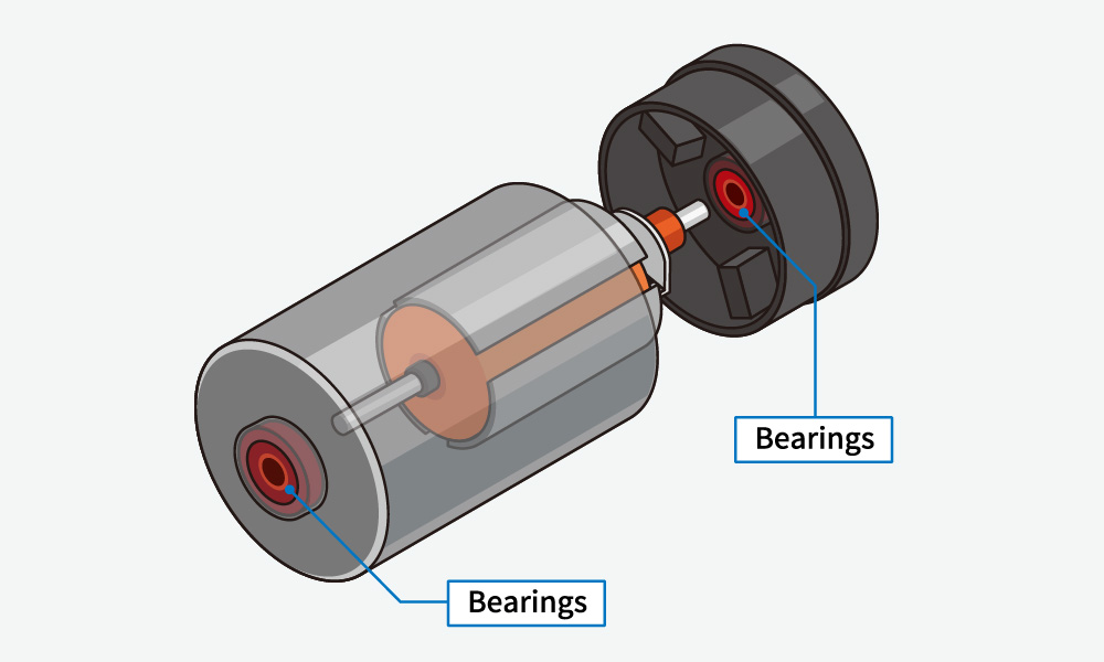
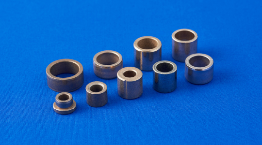
When compacting and sintering metal powders, tiny pores are generated between particles. The pores of oil-impregnated sintered bearings are impregnated with lubricant. The oil-impregnated sintered bearings contain lubricant in the bearings, so they are functional parts with a self-lubricating function. Because of superior mass productivity and homogeneous properties that are the characteristics of powder metallurgy, they are used in a wide variety of applications, such as bearings for motors.
The oil circulation mechanism of oil-impregnated sintered bearings
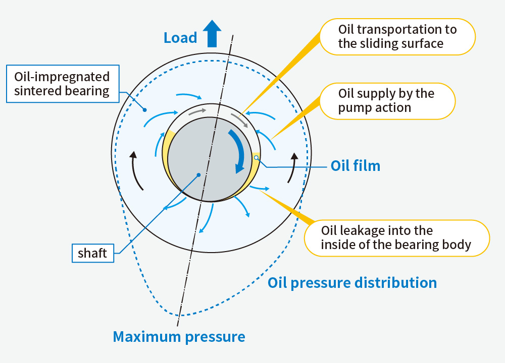
In an oil-impregnated sintered bearing, a pump action is produced by the rotation of a shaft so that oil is supplied from inside the bearing to the clearance between the shaft and the bearing to form an oil film. Although the oil film leaks into the pores at the bottom of the sliding surface, the oil is circulated in the bearing by the pump action and is then supplied to the clearance between the shaft and the bearing again. When the shaft stops, the oil is absorbed into the pores inside the bearing. This mechanism enables retention of a semipermanent and stable sliding state with no need for constant lubrication.
Examples of Use Applications of Oil-Impregnated Sintered Bearings
Power window
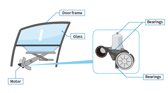
For the bearings in motors that are used irregularly, such as the motors for power windows, it is necessary to form an oil film between the shaft and the bearing instantaneously, even during unstable operation while maintaining sliding performance, as well as to supply reliable material at low cost for severe low speed and high load use conditions. By focusing air permeability and pores on the surface that lead to the formation of oil films to optimize the materials, we successfully developed highly durable, reliable, and cost-effective material.
Starters
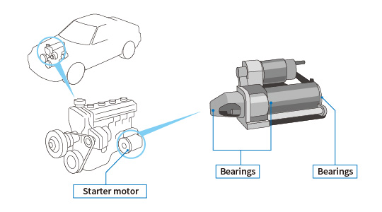
Starter motors start engines. The motor section is designed to rotate at high speeds to generate high torque. In recent years, the need for smaller size and lighter weight has been increasing more than ever before, and oil-impregnated sintered bearings that can withstand high-speed rotation and high torque are required to ensure superior sliding performance, wear resistance, and reliability. Different types of oil-impregnated sintered bearings, such as bearings supporting an armature (a rotating part of an electricity generator with a wire wound around the core), bearings for planetary gears, bearings for the output section, are used in combination in a starter motor, and many of our bearing products are used.
Wipers
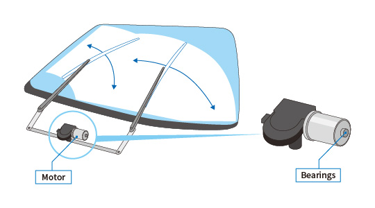
Wiper motors secure visibility by eliminating raindrops and snow from windshields. Because any stoppage due to failure could lead to a major accident, high reliability and wear-resistant materials are required. In addition, because of the need for a decrease in weight and size and the high torque applied to the bearings, high-strength materials are necessary. We offer wear-resistant and high-strength material for oil-impregnated sintered bearings and also provide many bearings for wiper motors.
Fuel pump
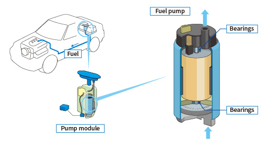
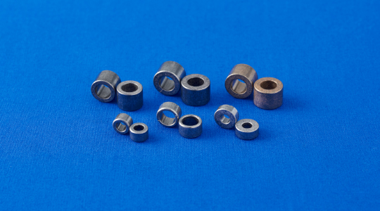
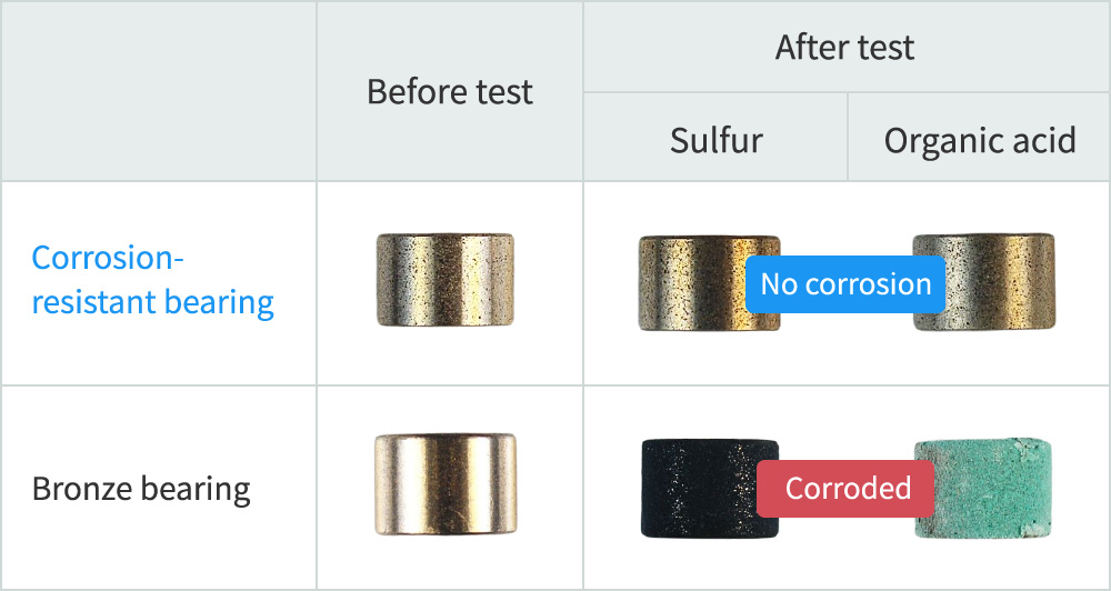
Fuel pumps are built into fuel tanks for putting fuel into engines. They are soaked in fuel at all times, and the bearing properties and corrosion resistance are required under a severe sliding environment against low-quality gasoline containing impurities. Our corrosion-resistant bearings exhibit superior corrosion resistance, wear resistance, and bearing performance even in gasoline containing highly concentrated sulfur or organic acid, and they are used globally and widely.
Electronic throttles
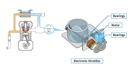
The engine throttle mechanism controls intake air volume and engine output by regulating the throttle opening degree. Conventionally, a throttle was operated by the amount of depression of the accelerator pedal by the driver via a wire. On the other hand, a electronic control throttle regulates the throttle using a motor via an electronic control unit (ECU) based on sensor that measures the degree of opening of the accelerator pedal. Because electronic control throttles offer finer control of the intake air volume than mechanical throttles, an improvement in fuel efficiency and a reduction in harmful exhaust gas can be achieved.
Our bearings are used in motor regulate the degree of opening of the throttle valve. Since electronic control throttles are placed near the engines, they need to be able to function in a wide temperature range and have vibration resistance.
Therefore, the bearing, made by impregnating Fe-Cu based material whose surface is controlled to be Cu rich with special fluorine oil that is applicable to a wide temperature range, must exhibit superior performance in wear resistance, friction coefficient, and seizure resistance and contribute to improvements in fuel efficiency, reductions in harmful exhaust gas, and significant reductions in costs.
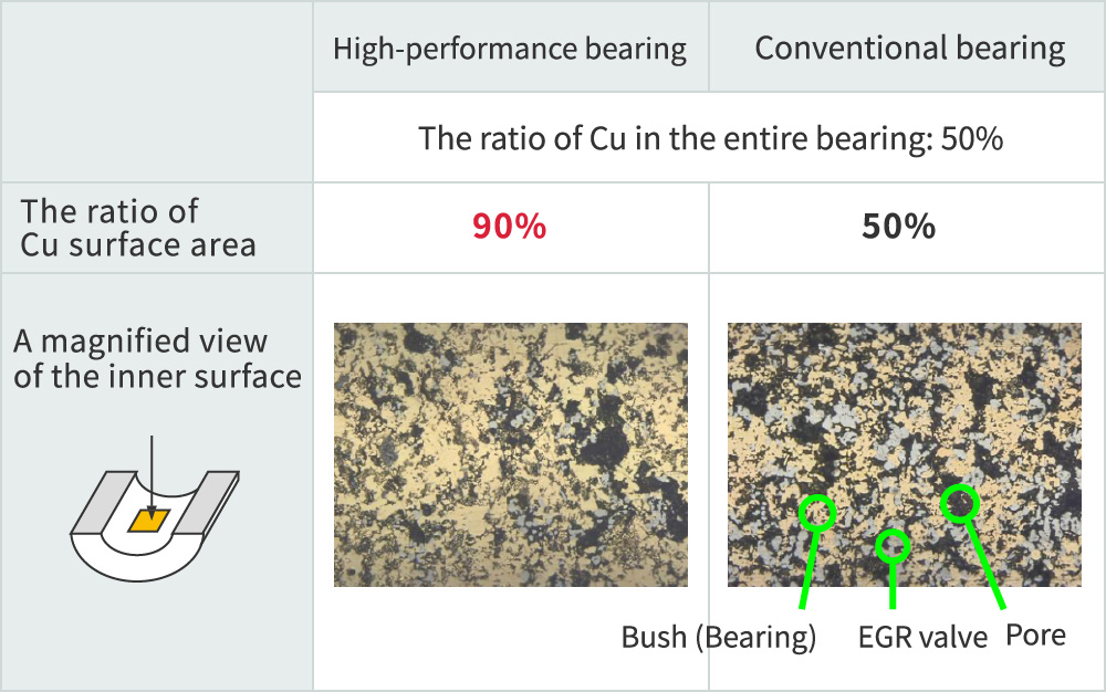
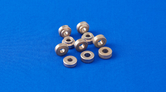
EGR(Exhaust Gas Recirculation)
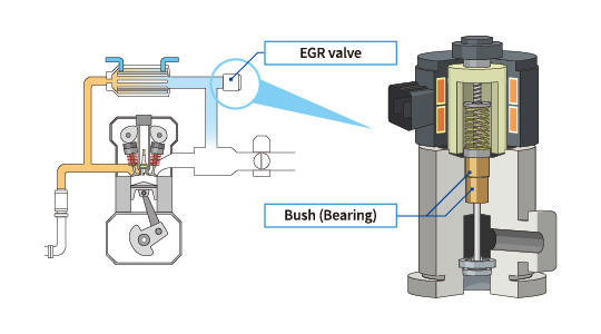
Exhaust gas recirculation (EGR) returns part of the exhaust gas from an automobile engine to a combustion chamber; this system is in widespread use to reduce NOx and fuel consumption. The bush for EGR is used for the valves that lead part of the exhaust gas to the intake air side and is used in an exhaust gas environment with a wide temperature range from ambient temperature to high temperatures where lubricants cannot be used. Therefore, we have realized material with superior self-lubricating property at high temperatures and oxidation resistance by adding a large amount of solid lubricant to the bearing material, which contribute to a reduction in NOx emitted and the fuel consumption of automobiles.
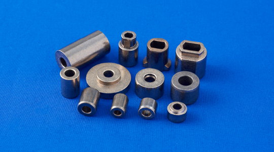
Sintered Bearing Forming Technique (patented)
Bearings for resin inserts
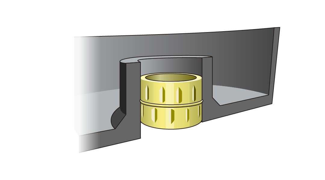
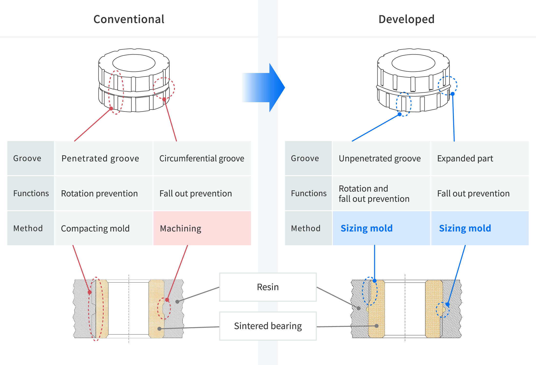
Although sintered bearings are generally press-fit into housings for use, housings are increasingly resinified and associated with the reduction in costs and the weight of motors. As a result, the need for sintered bearings that are suitable for resin inserts has been increasing. Because resin inserts have lower fastening power compared to press-fitting, it is necessary to implement measures to prevent the bearings with such inserts from rotating and falling out the thrust direction.
In the typical examples of bearings that have already been put into practical use, grooves were formed in the axial direction on the outer periphery of the bearings to prevent rotation, and grooves were also machined in the circumferential direction on the outer periphery to prevent falling out in the thrust direction. Although a reduction in costs was one of the purposes of the resinification of housings, a significant increase in bearing prices due to machining was a problem for customers. Therefore, we developed sintered bearings suitable for resin inserts that are formed in the process to prevent rotation and falling out in the thrust direction without any machining by using our unique forming technique. These bearings are increasingly used each year and contribute to cost reductions by customers.
Application as sliding materials
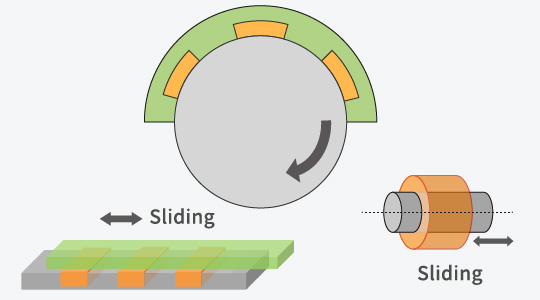
Our bearings can be used for rotating shaft and as sliding materials.
Thin-Walled Sintered Oil-Impregnated Bearings
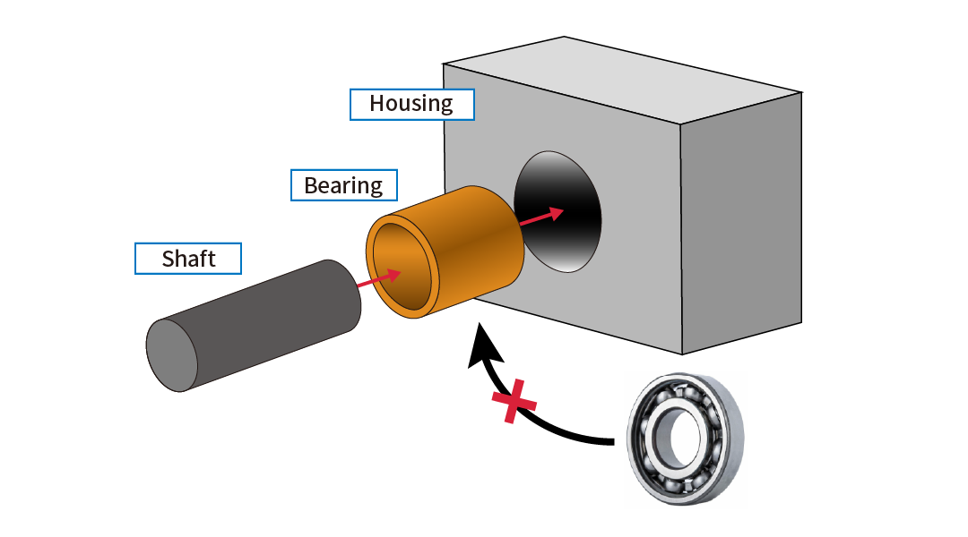
Diamet Proposes Replacing Wrapped Bushings and Ball Bearings with Sintered Oil-Impregnated BearingsWrapped bushings typically require costly surface treatments to achieve self-lubrication. In contrast, sintered oil-impregnated bearings offer excellent sliding performance at lower cost, thanks to the inherent properties of the base material and oil retention within the pores.Moreover, Diamet’s sintered bearings can be manufactured with inner and outer diameters under 1 mm, enabling installation in narrow gaps—such as the 1 mm clearance between a shaft and housing—where ball bearings are structurally impractical.

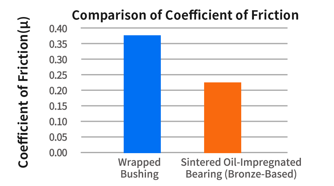
<Test Conditions>
Bearing: Inner diameter φ4 mm, overall length 8 mm
Sliding speed: 35 m/min
Surface pressure: 1 MPa
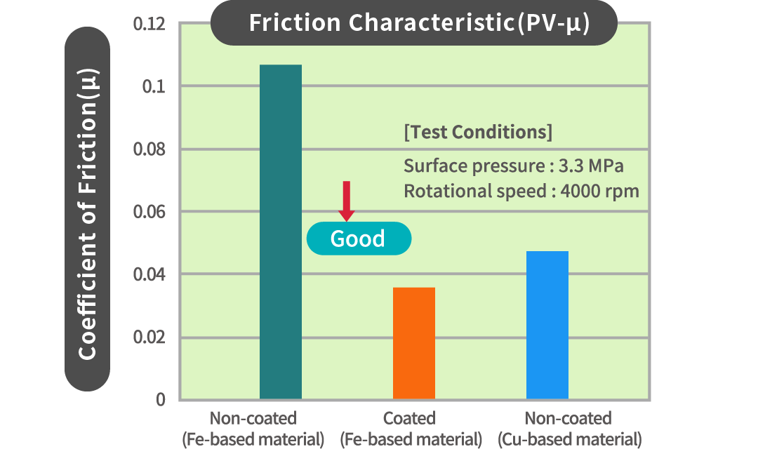
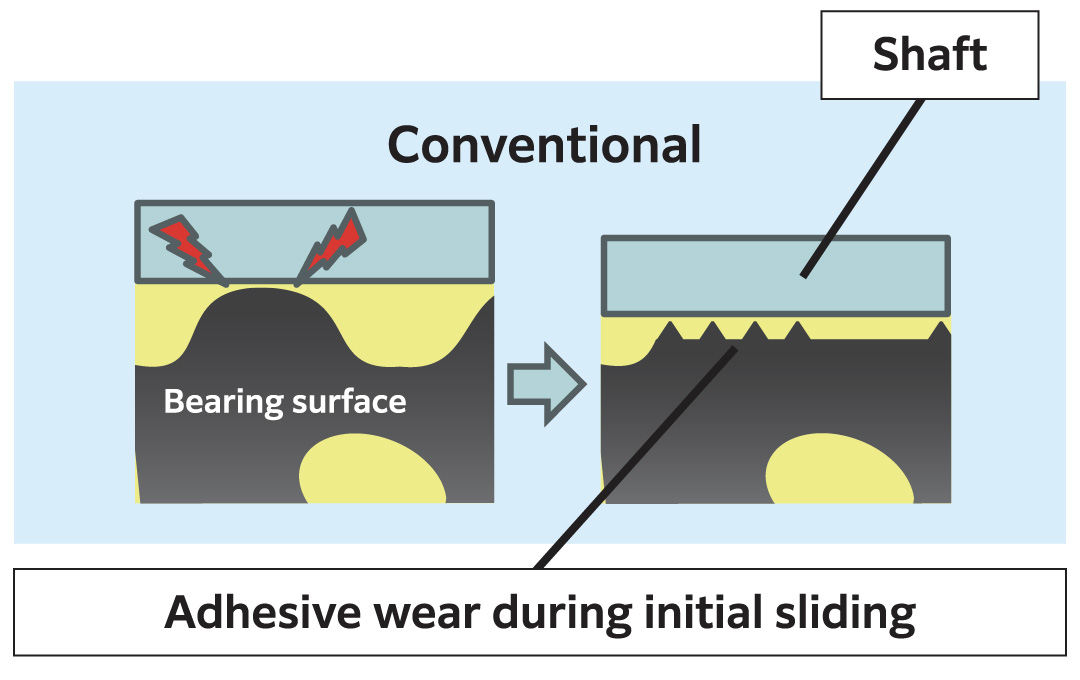
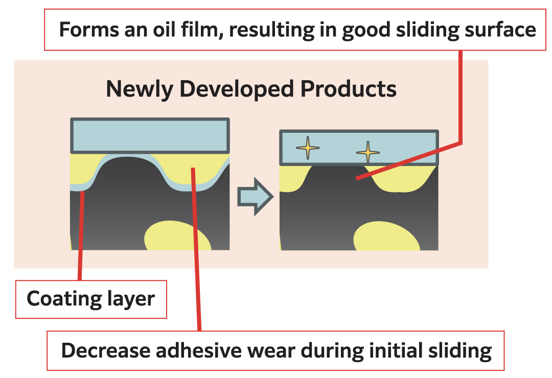
Sintered oil-impregnated bearing for high-velocity applications
By applying our proprietary surface coating to the bearing, we reduce the copper content in the raw powder, achieving both lower material costs and a reduced coefficient of friction.
Furthermore, a synergistic effect between the impregnated oil and the lubricant in the coating enables even lower friction.
This contributes to energy savings by reducing motor power consumption, and allows for material replacement from Fe-Cu alloys to more recyclable and cost-effective Fe-based materials, thereby reducing environmental impact.
Materials list for Oil-Impregnated Sintered Bearings / Sintered Bearings
About Sintered Machine Parts
The sintered machine parts that we manufacture through the powder metallurgy method are used in a variety of applications—engine parts, transmission parts and different types of sensors. By taking advantage of high precision, complicated shapes, and high productivity, which are unique to the powder metallurgy method, we offer iron- and stainless steel-based products according to demand characteristics at low costs.
Sintered Machine Part Products
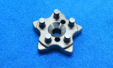
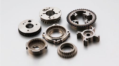
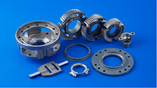
Variable valve parts
We manufacture components for variable valve timing mechanisms. For these parts that require high precision and strength, we contribute to the reduction in product costs through the realization of complicated shapes with multistage compacting technology, elimination of machining processes by forming with high-precision die assemblies, and increases in strength with the high-density manufacturing method.
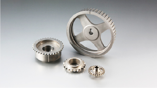
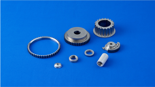
Sprockets and pulleys
We offer machining-less, low-cost, and high-precision sprockets and pulleys. We mainly manufacture roller chain and silent chain types of sprockets. In particular, we apply densification technology to silent chain type sprockets that require high strength to consistently provide high performance products.
Oil pump rotors
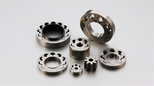
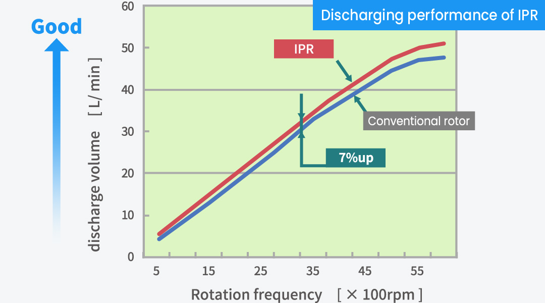
IPR® (Intelligent-Profile-Rotor) is our original sintered oil pump rotor with a patent-pending tooth profile characterized by high discharge efficiency, low friction, and low noise. The rotor contributes to the realization of low fuel consumption and superior quietness. By taking advantage of high efficiency, we produce high performance in the manufacture of compact rotors in electric oil pumps. Furthermore, as a design service, we customize tooth profiles and propose port shapes according to customer needs.
Transmission parts
We manufacture parts for automatic transmissions (AT), manual transmissions (MT), and continuously variable transmissions (CVT). To meet the needs for high precision, high strength, and complicated shapes, we offer products ranging from compact ones to large ones as desired at low costs.
Sintered Stainless-Steel Part Products
We manufacture sintered stainless-steel parts such as exhaust system components and sensor rings for brakes. Because such parts are used in severe high-temperature environments, high corrosion resistance and anticorrosion properties are required. We offer products in accordance with different usage environments and demand characteristics at low cost.
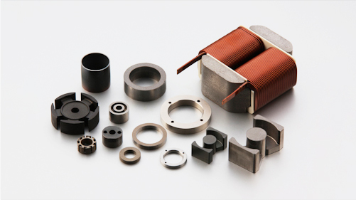
About Soft Magnetic Materials
Soft magnetic materials, unlike permanent magnets, are magnetized only when an external magnetic field is applied, and the magnetization disappears when the field is removed. They are used in magnetic components such as motor stators, reactors, and transformers. We manufacture sintered soft magnetic materials for low-frequency applications and powder magnetic cores for high-frequency applications. Sintered soft magnetic materials feature complex and near-net shapes that take advantage of the design flexibility unique to powder metallurgy. Powder magnetic cores are characterized by high electrical resistance and low loss because each metallic magnetic powder particle is insulated. With our unique insulation coating technology, we develop and manufacture powder magnetic cores with high magnetic flux density and low iron loss, offering a lineup ranging from pure iron-based to alloy-based cores such as sendust and amorphous types.
Soft Magnetic Material Products
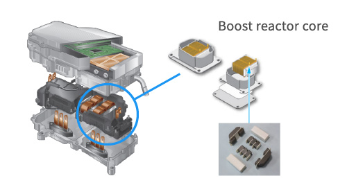
Cores for boost reactors
Boost reactors are used in circuits that increase electric voltage to the level required to drive motors. We manufacture block cores, U cores, E cores, PQ cores, and cores with different shapes.
*A power control unit for a hybrid automobile
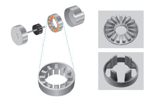
Cores for motors
We impart dimensional shapes that cannot be realized with magnetic steel sheets to achieve the downsizing of motors. We can shape cores for axial gap motors, brimmed cores for radial cap motors, and claw-pole cores.
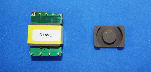
Cores for high-frequency
Cores for high-frequency are used in industrial equipment, as well as DC-DC converters and onboard chargers for electric vehicles (xEV) including hybrid electric vehicles (HEV) and battery electric vehicles (BEV). We are in the process of developing alloy cores that are compatible with several tens to several hundreds of kHz.
Materials list for powder magnetic
We provide custom services ranging from selection of soft magnetic materials to design and commercialization according to applications and characteristics.
For details, please contact us via The contact formorTEL:025-275-8172(Product inquiries)
| Series | Materials | Types | Magnetic properties | Application | |||||||||||
|---|---|---|---|---|---|---|---|---|---|---|---|---|---|---|---|
| Maximum relative permeability | Magnetic flux density | Iron loss | |||||||||||||
| 2kA/m T |
10kA/m T |
1T/ 400Hz kW/㎥ |
0.1T/ 10kHz kW/㎥ |
0.02T/ 100kHz kW/㎥ |
0.02T/ 300kHz kW/㎥ |
||||||||||
| MF | MF10 | Sintered Mgnetic Materials |
1,500 | 1.30 | 1.53 | ― | ― | ― | ― | Motor Relay Solenoid |
|||||
| MF19 | 3,000 | 1.40 | 1.61 | ― | ― | ― | ― | ||||||||
| MBS | MBS-S20 | Powder magnetic core | 700 | 1.22 | 1.67 | 470 | ― | ― | ― | Motor | |||||
| MBS-F20 | 350 | 0.82 | 1.47 | 420 | ― | ― | ― | ||||||||
| MBS-418 | 500 | 1.04 | 1.60 | 410 | ― | ― | ― | ||||||||
| MBS-207 | 550 | 0.94 | 1.48 | 380 | ― | ― | ― | ||||||||
| MBS-450 | 500 | 1.05 | 1.55 | 230 | ― | ― | ― | ||||||||
| MBS-R | MBS-RL200 | 250 | 0.62 | 1.36 | ― | 170 | 130 | 615 | Inductor | ||||||
| MBS-R3 | 200 | 0.48 | 1.27 | ― | 130 | 115 | 650 | ||||||||
| MBS-RA | MBS-RA5 | 150 | 0.38 | 0.99 | ― | 100 | 70 | 400 | |||||||
| MBS-RXA6 | 70 | 0.18 | 0.57 | ― | 35 | 30 | 240 | ||||||||
| MBS-RXA7 | 45 | 0.11 | 0.40 | ― | 33 | 20 | 90 | ||||||||
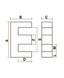
EE Core Lineup, Dimensions, AL Values, B-H Characteristics, and Core Loss (MBS-RXA6)
Details
| No. | A (mm) |
B (mm) |
C (mm) |
D (mm) |
E (mm) |
F (mm) |
L (mm) |
M (mm) |
Path length (mm) |
Cross section area (mm²) |
AL value (@B=0T) (nH/N²) |
AL value (@B=0.3T) (nH/N²) |
|---|---|---|---|---|---|---|---|---|---|---|---|---|
| EE25 | 25.0 | 10.25 | 13.5 | 6.3 | 18.1 | 6.9 | 3.45 | 5.6 | 44.4 | 97.65 | 304 | 152 |
| EE28 | 28.0 | 11.00 | 13.8 | 6.5 | 20.0 | 8.0 | 4.0 | 6.0 | 46.0 | 115.00 | 346 | 173 |
| EE30 | 30.0 | 11.70 | 14.0 | 6.7 | 21.0 | 9.0 | 4.5 | 6.0 | 46.8 | 130.67 | 386 | 193 |
| EE33 | 33.0 | 12.55 | 14.5 | 6.9 | 22.7 | 10.3 | 5.15 | 6.2 | 48.0 | 154.18 | 444 | 222 |
| EE35 | 35.0 | 13.10 | 15.5 | 7.1 | 24.0 | 11.0 | 5.5 | 6.5 | 49.4 | 175.67 | 492 | 246 |
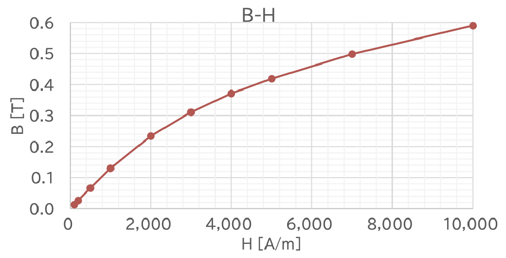
BH
Iron loss

※All figures are representative.
※BH and Iron loss were measured using O.D.35-I.D.25-H5 toroidal core. Characteristics may vary depending on the product shape.
※We also provide custom services ranging from the selection, design, and commercialization of soft magnetic materials based on specific applications and characteristics.
New Compact Design Technology for DC-DC Converters
DC-DC converters utilizing transformers can generally be categorized into ON-OFF type for low power applications, which requires fewer components and results in a compact size, and ON-ON type for high-power applications, which involves more components and results in a larger size. Traditionally, ON-ON types have been used where high power is required. Furthermore, ferrite has been the common choice for the magnetic core material of transformers due to its magnetic properties and compatibility with the operating modes.
Achieving miniaturization of passive components in ON-ON converters necessitates increasing the operating frequency, but this also leads to a decline in power conversion efficiency.
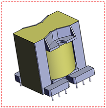
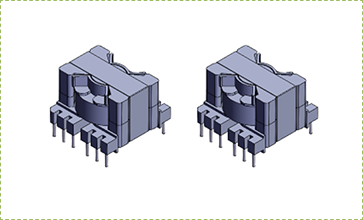
The new circuit topology proposed by our company, the isolated “TriMagiC Converter™,” replaces ferrite with our proprietary magnetic material “MBS™,” which features low permeability, high saturation magnetic flux density, and low loss. Powdered cores are used for the magnetic components of the transformer and resonant inductor. Our prototype testing has confirmed that by utilizing “MBS™” in an ON-ON & ON-OFF operating mode circuit, we can simultaneously achieve high conversion efficiency and significant size reduction—reducing the total volume of magnetic components to one-third of conventional designs while still handling high power.
The isolated “TriMagiC Converter™” achieves miniaturization and high efficiency of Switched Mode Power Supplies without the use wide band-gap devices such as SiC or GaN, even utilizing conventional Si switching devices.
Moreover, replacing conventional phase-shifted converters with this new topology is straightforward. This document provides an overview of the features of the new circuit topology.
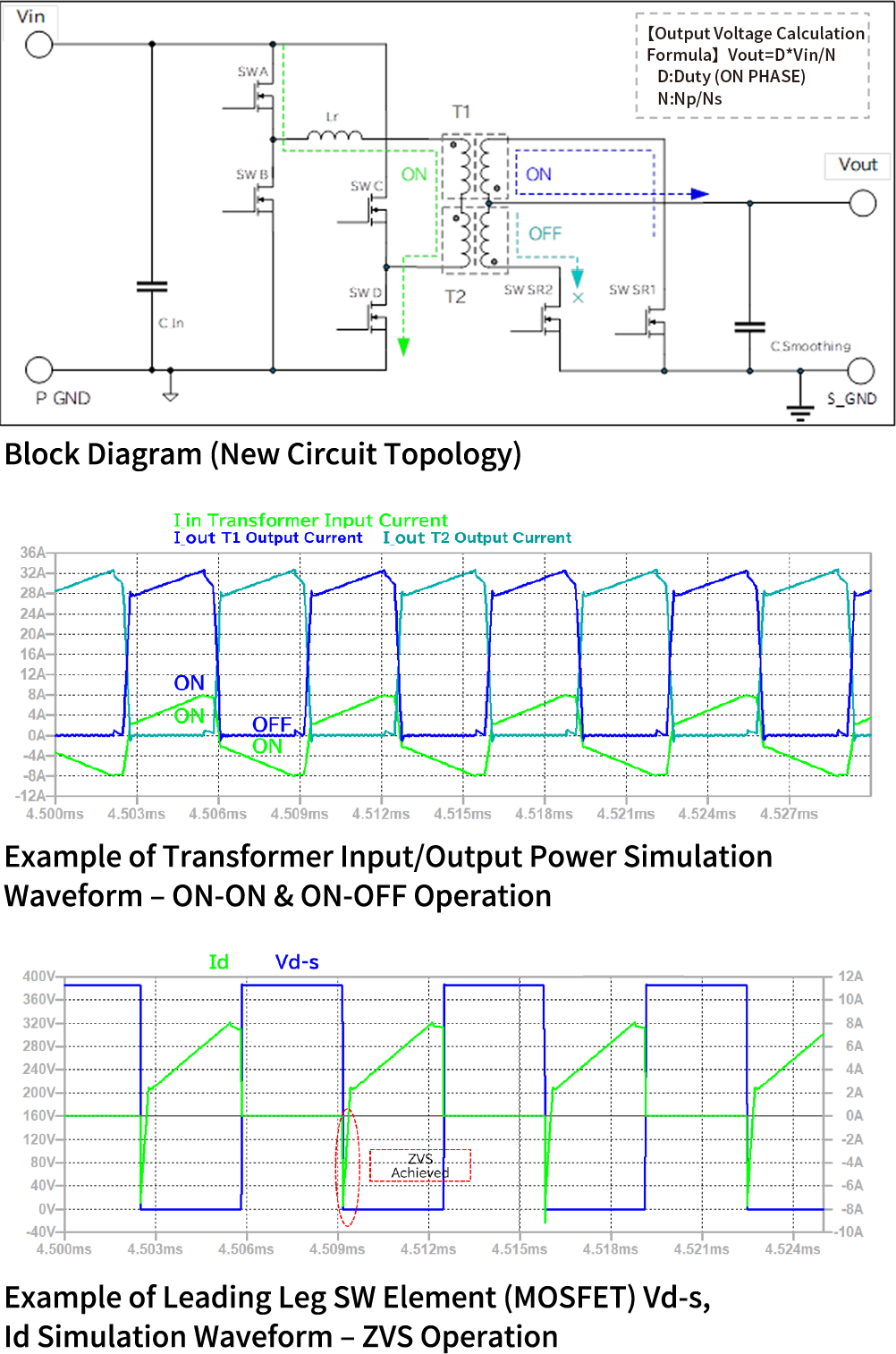
Principle: Circuit Configuration and Basic Operation of the Isolated “TriMagiC Converter™” (Phase-Shift Control)
The isolated “TriMagiC Converter™” proposed by our company utilizes two transformers with identical characteristics, featuring low permeability and high saturation magnetic flux density. The primary windings of these transformers are connected in series on the input side, while the secondary windings are connected in parallel (or in series) with reversed polarity, along with rectifying elements.
When power is supplied from the bridge circuit, one transformer operates in ON-ON mode, while the other operates in ON-OFF mode. As the polarity of the bridge circuit reverses, the operation modes also switch, with ON-ON and ON-OFF modes alternating continuously.
By appropriately inserting a resonant inductor and setting an optimal dead time for the output capacitance of the switching element (MOSFET), Zero Voltage Switching (ZVS) can be achieved, enabling soft switching.
Furthermore, the drive timing of the switching elements (MOSFETs) and synchronous rectification elements (SR MOSFETs) in this new circuit topology remains the same as that of a conventional full-bridge phase-shift converter.
Features of the Isolated “TriMagiC Converter™”
– Comparison with Conventional Topologies
Significant Miniaturization
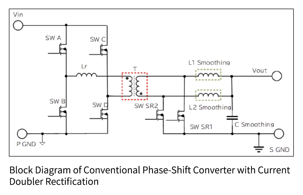
When estimating the core size of the main transformer and smoothing inductor for a 1.6 kW phase-shift converter with current doubler rectification operating at 100 kHz, the expected core selections are:
Main transformer: PQ5050
Smoothing inductor: PQ3230 × 2
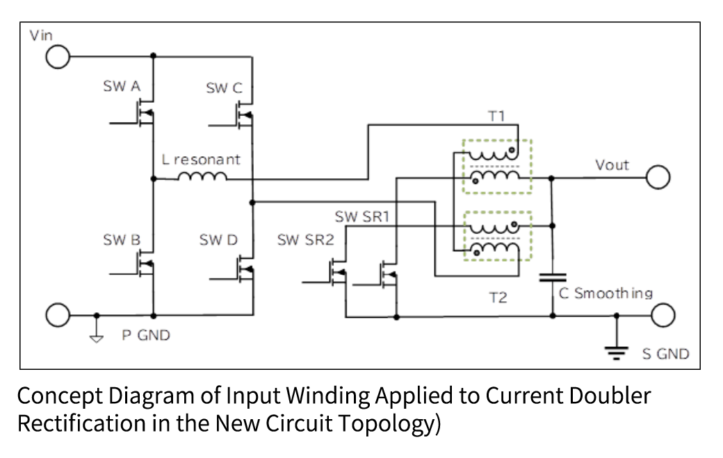
In the new circuit topology, the main transformer is designed so that the input winding is directly applied to the smoothing inductor of the current doubler rectification Topology. As a result:
The main transformer in conventional circuits becomes unnecessary.
The magnetic energy of the new main transformer is equivalent to that of the smoothing inductor in the conventional Topology.
Since the design can be realized using only the smoothing inductor’s magnetic energy, significant size reduction is achieved.
Considerations for Miniaturization
Although the new circuit topology requires only the smoothing inductor of the conventional Topology, the output current becomes a half-wave, resulting in:
An increase in RMS current by a factor of √2, requiring additional winding space and lower resistance.
However, since the conventional main transformer is no longer needed, the benefit of miniaturization outweighs the increased winding requirements.
As a result, the total volume of magnetic components in the new circuit Topology is approximately one-third of that in the conventional Topology.
Comparison of Magnetic Components: Conventional vs. New Topology
Design conditions: Input: 360–390V, Output: 54V 30A (1.62 kW), Operating Frequency: 100 kHz
| New Circuit Topology | Conventional Topology | ||||
|---|---|---|---|---|---|
| Selected Core for Transformer | EQ3222A/32x22x20 x2pcs | PQ5050/50x32x50 | |||
| Magnetic Component Volume | 14,080mm³x2=28,160mm³ | 80,000mm³ | |||
| Input Coil Turns | 27turns | 30turns | |||
| Turns Ratio (Np/Ns) | 3:1 | 3:1 | |||
| Input Coil Inductance | 135uH | — | |||
| Output Coil Inductance | 15uH | — | |||
| Peak Magnetizing Current / Bm | 8.26A / 0.28T | — | |||
| Magnetizing Current / ΔB (p-p) | 6.71A / 0.23T | — / 0.36T (±0.18T) | |||
| Selected Core For Smoothing Inductor | ーーー | EQ3222A/32x22x20 x2pcs | |||
| Magnetic Component Volume | 14,080mm³x2=28,160mm³ | ||||
| Inductance (Turns) | — | 33uH(13ターン) | |||
| Peak Magnetizing Current / Bm | — | 19.5A / 0.32 T | |||
| Magnetizing Current / ΔB (p-p) | — | 8.9A / 0.15T | |||
| Total Magnetic Component Volume | 28,160mm³ | 108,160mm³ |
Output Smoothing Capacitor Miniaturization
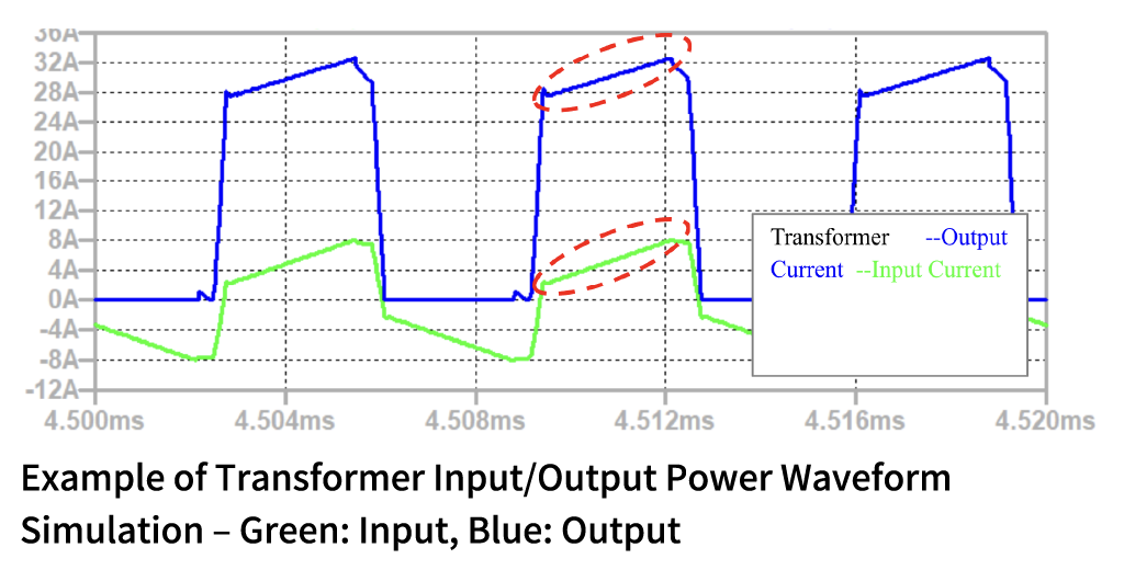
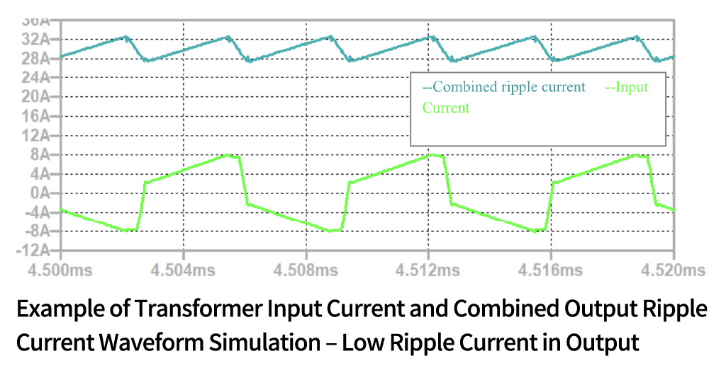
In ON-ON mode, the slope of the output current from the transformer is gentler than that of the magnetizing current during ON-OFF mode because the energy stored in the ON-OFF period is also released. Specifically:
The slope of the output current is approximately half of that of the magnetizing input current.
The ripple current flowing into the output smoothing capacitor is reduced because it consists of a combined current from the two transformers, further lowering its value compared to the conventional topology.
As a result, the required output smoothing capacitance is reduced to approximately half of that in the conventional topology.
Reduction of Core Losses (Magnetic Flux Density Variation)
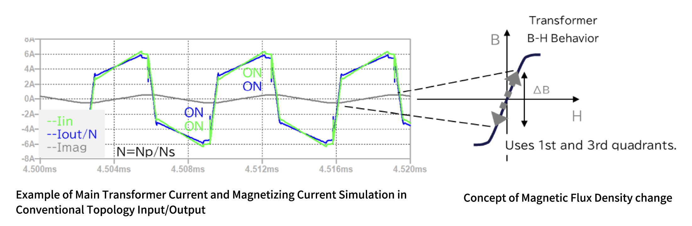
(A) Transformers in Conventional Topology
In conventional ON-ON (and ON-ON) operation, the change in magnetic flux density of the transformer is large even small magnetizing current, due to Ferrite’s high permeability. It increases core losses.
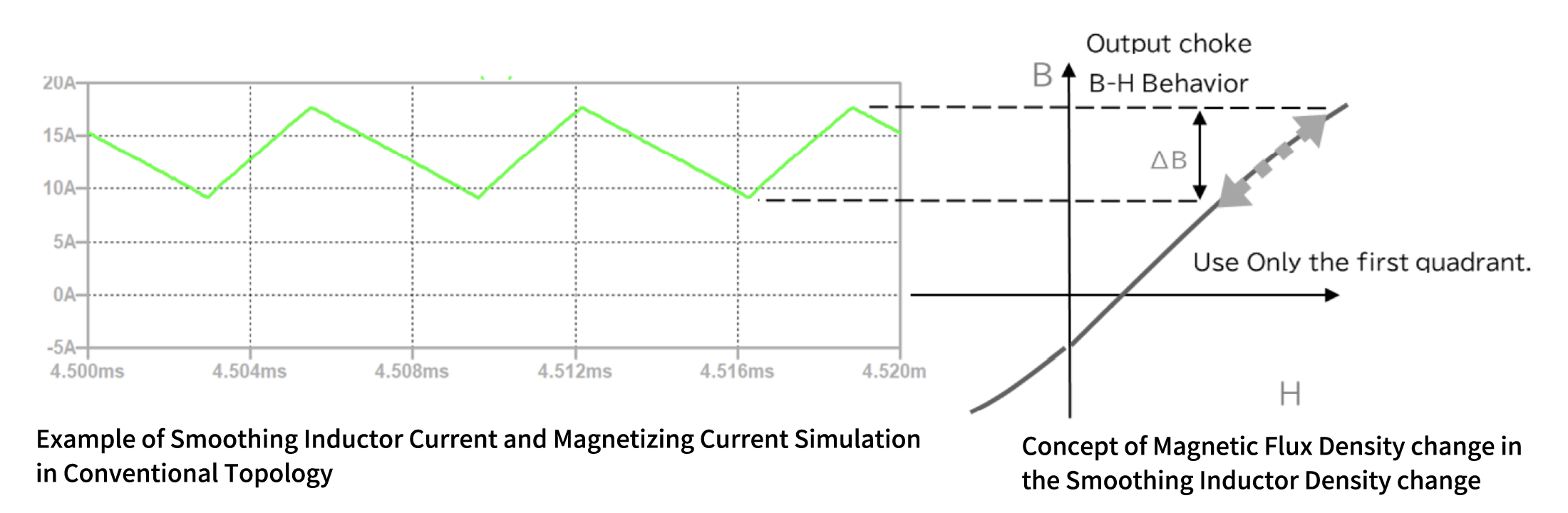
(B) Smoothing Inductors in Conventional Topology
In conventional topology, Smoothing Inductor’s inductance value is generally set to which output ripple current should be around 25-30% of output current. Since the ripple current is equivalent to the magnetizing current, the magnetic flux density variation remains relatively small, resulting in lower core losses compared to the main transformer.
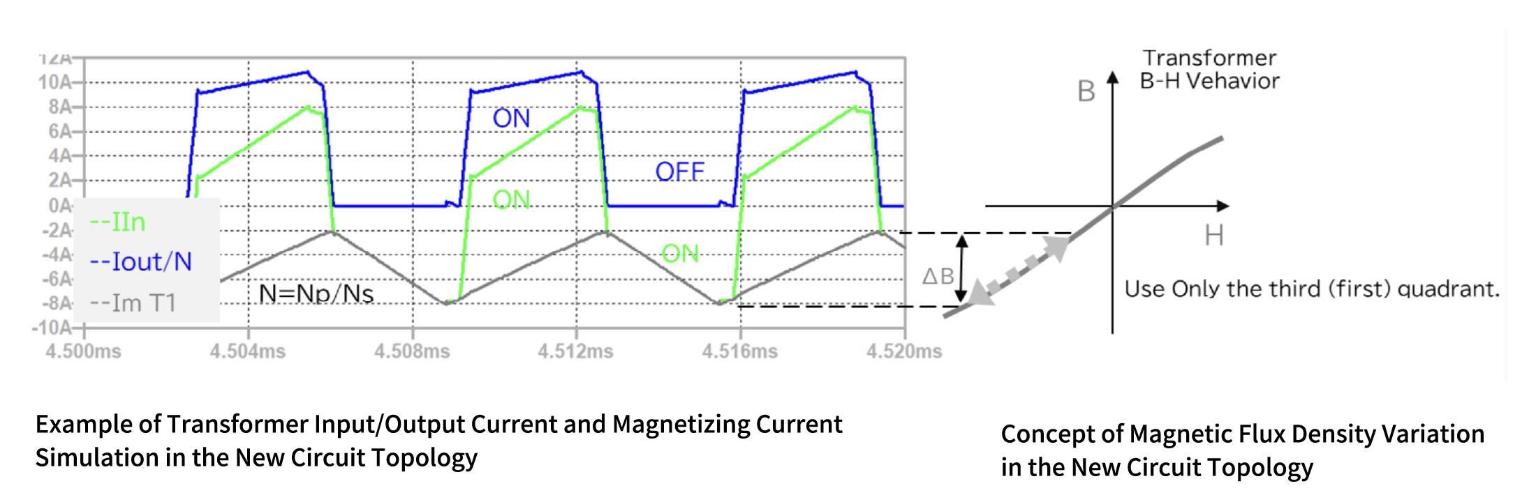
(C) Transformers in the New Circuit Topology
In the new circuit topology, the magnetizing currents in ON-ON and ON-OFF mode operation partially cancel flux density. It significantly reduces the magnetic flux density change (ΔB). This operation reduces significant core losses.
Key benefits:
The magnetic flux density change behaves similarly to that of the smoothing inductor in conventional topology, reducing core losses.
Since there is no component equivalent to a transformer as in conventional topology, no equivalent core loss occurs.
Due to the presence of an ON-OFF period, the transformer’s magnetic core should be low in permeability value to avoid saturation.
Because the magnetic flux density operates with a bias, selecting a magnetic material with high saturation flux density is preferable.
Core loss is generally proportional to the frequency raised to the power of 1.5 to 1.8, and to the magnetic flux density variation raised to the power of 2.2 to 2.8, depending on the material. In the new circuit topology, the reduced magnetic flux density variation significantly lowers core losses.
Prototype Example
For our prototype, we aimed for further miniaturization by designing the circuit to operate at 150 kHz.
Core selection for the transformer: EE3023×2 pcs
Confirmed power conversion efficiency: 97%
By utilizing low-permeability powdered cores for the main transformer and adopting the ON-ON & ON-OFF operating mode, we achieved:
Approximately 1/3 reduction in the size of magnetic components compared to conventional topologies.
Approximately 2/3 reduction in power board size compared to conventional designs.
Conclusion
Compared to conventional topologies, the new circuit topology offers the following advantages:
- Significant miniaturization
- Without increasing the operating frequency, the size of magnetic components and output capacitors can be drastically reduced.
- Reduction of magnetic component losses
- Lower magnetic flux density variation results in lower core losses.
- No increase in losses other than non-magnetic components
- The circuit configuration and pulse drive timing remain the same, ensuring that losses in non-magnetic components are unchanged.
- Same drive timing as conventional full-bridge phase-shift converters
- No changes are required for the drive timing of each device.
| Topology /Switching Mode |
Transfoormer Mode |
Complexity /Cost |
Transistor Switching loss |
Transformer Loss |
Transformer Volume |
Output Ripple |
Features | ||||||||
|---|---|---|---|---|---|---|---|---|---|---|---|---|---|---|---|
| Fly Back /Hard Switching |
ON-OFF | Low/1 | Large | Large | Large | Largest | Simplest circuit configuration /Low cost /for Low power |
||||||||
| RCC (Fly Back) /Quasi ZVS |
Low/1 | A bit Large | Large | Large | Largest | Simplest circuit configuration /Low cost /For low power /Slightly lower switching loss |
|||||||||
| Half-Wave Current Resonance /ZVS |
A Little/2 | Small | Large | Large | Largest | Circuit configuration A little complicated /low switching loss |
|||||||||
| Forward /Hard Switching |
ON-ON (OFF-OFF) |
A Little/1.5 | Large | A Little Large | A Little Large | Low | Simple circuit configuration /for medium power |
||||||||
| Active Clump Forward /ZVS |
A Little/2 | A bit Large | A Little Large | A Little Large | Low | Forward converter switching: Loss reduction |
|||||||||
| half Bridge /Hard Switching |
ON-ON (ON-ON) |
A Little/2 | A bit Large | Large | Small | Low | Circuit configration a little complicated | ||||||||
| Half Bridge LLC/ZVS |
A Little/2 | Lowest | Large | Small | Large | Minimal switching loss due to current resonance / Large output ripple current / Complex circuit configuration |
|||||||||
| Full Bridge Phase Shift / ZVS |
Very/4 | Low | Large | Small | Low | Complex circuit configuration /for high power applications |
|||||||||
| Full Bridge LLC Interleave /ZVS |
Most/5 | Lowest | Large | Small | Lowest | Minimal switching loss due to current resonance / Minimal output ripple current / Most complex circuit configuration |
|||||||||
| TriMagiC Full Bridge Phase Shift /ZVS |
ON-ON & ON-OFF |
Very/3.8 | Low | Lowest | Smallest | Lowest | Complex circuit configuration /minimal loss in magnetic components /minimal passive components |
Table 2: Simplified Comparison of Conventional and New Circuit Topologies
Contact Information
In addition to selling powdered cores, we also provide support for circuit design utilizing our proposed isolated “TriMagiC Converter™” (some support services may be fee-based).
Currently, we offer a free tool for simplified calculation of transformer design parameters when using the isolated “TriMagiC Converter™” with phase-shift control.
For more details about the isolated “TriMagiC Converter™” and powdered cores, or to request access to the simplified calculation tool, please visit:
Our product page on the IPROS manufacturing site
Our corporate website contact page
For Technical Inquiries Related to This Document
Diamet Corporation – Sales Planning & Development Department